How to Design a Wind-Solar Hybrid System: A Step-by-Step Diagram Guide
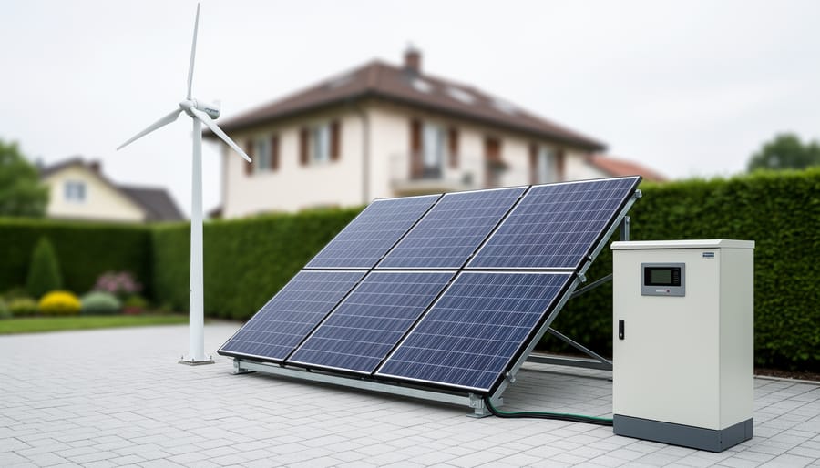
A wind solar hybrid system diagram is a comprehensive visual blueprint showing how wind turbines and solar panels integrate with batteries, inverters, and grid connections to deliver reliable renewable energy. Creating an accurate diagram typically takes 2-4 hours for a standard residential or small commercial installation and requires understanding both electrical architecture and European safety standards. The diagram serves as your primary communication tool with installers, engineers, and regulatory authorities, transforming abstract energy concepts into concrete implementation plans.
European homeowners and businesses pursuing energy independence in 2026 face a unique advantage: wind and solar resources complement each other naturally, with wind often peaking during winter months and cloudy periods when solar output diminishes. A properly structured diagram captures this synergy while addressing practical considerations like voltage matching, overcurrent protection, and harmonized grid synchronization. Whether you’re planning a 5kW residential setup in Bavaria or a 50kW commercial installation in Denmark, the diagram translates your sustainability goals into technical specifications that contractors can price, permit officers can approve, and installers can execute.
The complexity of hybrid systems demands more than sketching boxes and arrows. Your diagram must account for dual charge controllers, battery chemistry compatibility, smart switching logic, and backup power sequencing. This guide walks you through each component layer, from generation equipment through energy storage to consumption points, ensuring your final diagram supports efficient system operation while maintaining the safety margins required across EU member states.
Essential Components You’ll Need for Your Hybrid System Diagram

Hardware Components to Include
Every accurate wind-solar hybrid system diagram must include six fundamental hardware elements, each with specific technical details that installers and regulators need to verify your design.
Solar Panels: Your diagram should show the complete photovoltaic array with individual panel specifications, wattage per module, total array capacity in kW or kWp, and series/parallel configuration. Include mounting angle notation and orientation markers (typically south-facing in Europe) since these affect performance calculations and permit approval.
Wind Turbines: Mark turbine placement with hub height, rotor diameter, and rated capacity in kW. Small-scale residential systems typically range from 1.5 kW to 10 kW, while commercial installations may reach 50 kW or beyond. Your diagram needs tower type annotation and foundation requirements for structural verification.
Charge Controllers: MPPT or PWM controllers regulate power from generation sources to batteries. Show separate controllers for solar and wind inputs, with voltage and amperage ratings matching your system’s DC bus design, commonly 48V for residential European systems.
Inverters: The diagram must specify inverter type (string, hybrid, or bi-directional), AC output voltage (230V single-phase or 400V three-phase for European standards), and continuous/surge power ratings. Hybrid inverters combining solar and wind inputs simplify the design but require careful sizing.
Battery Storage: Indicate battery chemistry (lithium-ion, LFP, or lead-acid), total capacity in kWh, nominal voltage, and configuration topology. European systems typically use modular 2.5-5 kWh units in parallel or series arrangements.
Grid Connection Points: Mark the utility interface with bidirectional meter location, main service panel integration, and any required disconnect switches for safety isolation.
Software and Design Tools
Creating accurate hybrid system diagrams requires software that balances technical precision with clear visual communication. For European project submissions, your tool must produce scalable, professional outputs that installers and regulatory bodies can easily interpret.
Free and Low-Cost Options
SketchUp Free offers intuitive 3D modeling suitable for basic system layouts, though it lacks electrical schematic capabilities. LibreCAD provides 2D drafting with electrical symbol libraries, making it adequate for simple residential installations. PVsyst includes built-in diagramming tools alongside performance modeling, particularly valuable for solar-dominant hybrid systems requiring yield calculations.
Professional-Grade Platforms
AutoCAD Electrical remains the European industry standard, offering comprehensive symbol libraries, automated wire numbering, and DWG export compatible with most engineering workflows. EPLAN Electric P8 excels for complex commercial projects, with built-in compliance checking for IEC standards. Both produce documentation meeting VDE and CENELEC requirements.
Specialized Hybrid System Tools
HOMER Grid and RETScreen integrate economic analysis with technical diagrams, helping justify component sizing decisions. These platforms generate reports that combine visual schematics with performance data, strengthening permit applications for larger installations.
Choose software based on your project’s complexity and the submission requirements of your local distribution network operator.
Safety Considerations and Regulatory Requirements
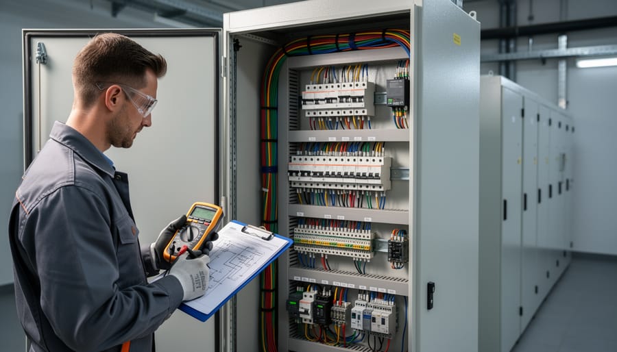
Electrical Safety Protocols
Your hybrid system diagram must clearly show all electrical safety measures to protect both installers and end-users. Start by marking voltage ratings at each connection point, solar arrays typically produce 48V DC in residential systems, while wind turbines can generate variable voltages up to 600V depending on wind speed. Every voltage transition point needs clear labeling.
Circuit protection is non-negotiable. Your diagram should indicate appropriately sized fuses or circuit breakers between each component: one between the solar array and charge controller, another between the wind turbine and its controller, and separate breakers for battery bank connections. Size these at 125% of maximum expected current to prevent nuisance tripping while maintaining protection.
Grounding appears as a dedicated conductor running from each metal component to your earthing system. Show separate grounding points for solar panel frames, wind turbine tower, inverter chassis, and battery enclosure. Use the standard earth ground symbol consistently.
Disconnect switches deserve prominent placement in your diagram. Position manual disconnects between generation sources and controllers, and between batteries and inverters. These allow safe maintenance isolation. Mark each switch location with clear labels indicating which circuit it controls.
European Grid Connection Standards
European grid operators require hybrid renewable systems to comply with specific technical standards before connection approval. Understanding these requirements ensures your diagram reflects compliant configurations from the outset.
EN 50438 establishes the baseline requirements across Europe for connecting micro-generators to low-voltage networks. Your diagram must show frequency and voltage protection relays that disconnect the system when grid parameters deviate beyond 47.5-51.5 Hz or ±10% nominal voltage. These protective devices prevent islanding, where your system continues energizing a de-energized grid section, creating safety hazards for maintenance crews.
German installations follow VDE-AR-N 4105, which mandates additional requirements for systems above 3.68 kVA. Include reactive power control capability in your inverter specifications and show the required external switch-disconnector accessible to grid operators. Systems exceeding 100 kW need dynamic grid support functions that stabilize voltage during faults.
France applies NF C 15-100 alongside EN standards, requiring specific surge protection devices rated for your combined wind and solar capacity. Spanish installations must comply with RD 244/2019, which sets stringent power quality limits on harmonic distortion.
Your diagram should annotate which standards apply to your location and show all required protection devices with their trip settings clearly marked. This documentation streamlines approval from your distribution network operator and prevents costly redesigns during permitting.
Step 1: Map Your Energy Generation Sources
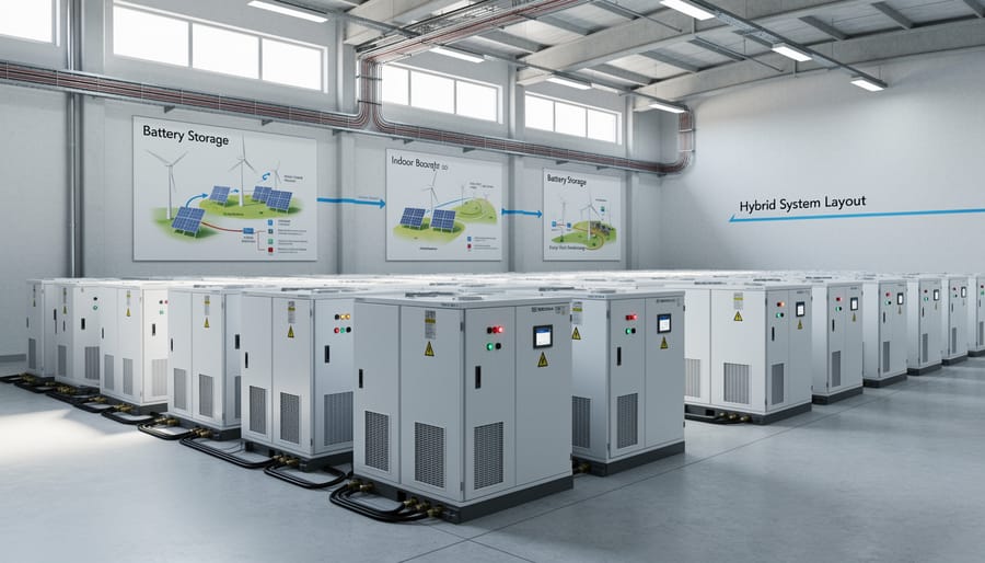
Begin with the top of your diagram by establishing clear positions for both solar and wind generation sources. Place solar arrays on the left side and wind turbines on the right, creating distinct zones that simplify troubleshooting and allow installers to understand power flow at a glance. This spatial separation also reflects real-world installation patterns common across European projects.
For each generation source, you need to document four critical specifications in sequence:
- Calculate and label the total generation capacity in kilowatts for each source, sum individual panel wattages for solar arrays and note the rated output for each turbine at standard wind speeds.
- Mark orientation and tilt angles using compass notation (e.g., 180° south-facing) and degrees from horizontal (typically 30-45° for European latitudes); for turbines, indicate hub height and rotor diameter.
- Specify exact panel or turbine models with manufacturer part numbers, this detail proves essential when installers verify compatibility with charge controllers and when authorities assess compliance.
- Indicate output voltage and current ratings at maximum power point, including whether sources deliver 12V, 24V, or 48V DC, as mismatches here cause the most common hybrid system failures.
Draw connection lines from each source using solid lines for positive conductors and dashed lines for negative returns. Label wire gauge specifications alongside these lines, particularly where multiple strings combine. European regulations require you show the exact point where solar and wind circuits converge before reaching the charge controller stage.
Use standard electrical symbols throughout: rectangles with diagonal lines for solar panels, three-bladed circles for wind turbines. Add compass roses near solar arrays and wind rose indicators beside turbines to communicate site-specific generation patterns. This attention to orientation detail helps engineers verify your design accounts for seasonal variations in European sun angles and prevailing wind directions.
Step 2: Integrate Charge Controllers and Power Management
Position your charge controller between the generation sources and battery bank, serving as the critical junction where wind and solar inputs converge. Start by drawing two parallel input lines: one from your solar array (marked with DC voltage and current ratings) and one from your wind turbine (noting AC-to-DC rectification if required). These lines feed into dedicated hybrid controllers that manage power flow from both sources simultaneously.
Choose between MPPT (Maximum Power Point Tracking) and PWM (Pulse Width Modulation) controllers based on your system voltage differential. MPPT controllers suit systems where panel voltage significantly exceeds battery voltage, common in 48V battery banks paired with high-voltage solar strings, and can boost efficiency by 15-30%. PWM controllers work when panel and battery voltages closely match, typically in smaller 12V or 24V configurations. Show this selection clearly on your diagram with controller model specifications.
Calculate required controller capacity by totaling peak generation from both sources, then add 25% headroom for safety. For a 3kW solar array and 2kW wind turbine, specify a controller rated for minimum 6.25kW combined input. In dual-input configurations, diagram separate charge regulation circuits for each source to prevent backfeed and optimize individual source performance.
Include essential protection elements in your diagram: inline fuses or circuit breakers on each input line (rated at 125% of source maximum current), surge protection devices for lightning strikes, and temperature sensors that adjust charging parameters. Draw clear labels showing voltage ranges, current capacity, and communication ports that connect to your monitoring system. Position disconnect switches on both input and output sides for safe maintenance access.
Step 3: Design the Battery Storage Layout
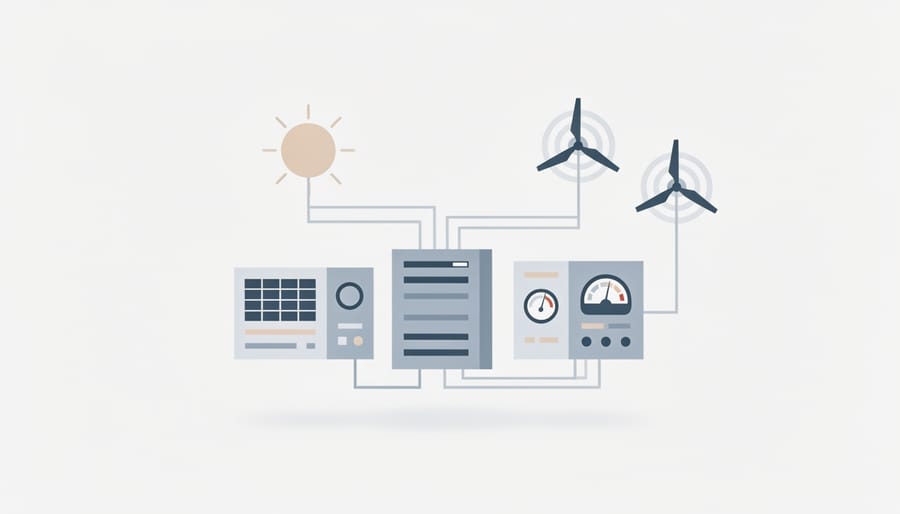
Battery storage forms the heart of your hybrid system diagram, buffering the intermittent outputs from both wind turbines and solar panels. Your diagram must clearly show how individual battery modules connect to form the complete storage bank, specifying both voltage and capacity parameters.
Start by determining your system’s DC bus voltage, typically 48V for residential installations or 120V-400V for commercial projects. This drives whether batteries connect in series (increasing voltage) or parallel (increasing capacity). Mark each string with voltage notation, and indicate parallel connections between strings to reach your total amp-hour target. For a 48V system delivering 20kWh storage, you might diagram four 12V batteries in series, with three such strings in parallel.
Position the Battery Management System (BMS) prominently in your layout. The BMS monitors cell voltages, temperature, and charge states across the entire bank. Show its connections to individual battery modules or strings, and indicate communication links to your inverter and monitoring system. For lithium-ion installations, the BMS must appear between the battery bank and charge controllers with clear disconnect capability.
European climates demand explicit temperature management notation. If using lead-acid batteries, show ventilation pathways for hydrogen off-gassing and indicate ambient temperature ranges (ideally 15-25°C). For lithium batteries, diagram heating elements for sub-zero protection and thermal sensors connected to the BMS. In Mediterranean regions, mark cooling provisions for summer operation above 30°C.
Include fusing or circuit breakers between each parallel string and the main bus bar. Specify wire gauges based on maximum current draw, and show the physical separation between battery terminals to prevent accidental shorts. Label positive and negative bus bars clearly, and indicate grounding points per EN 50438 requirements.
Step 4: Connect Inverters and Conversion Equipment
Your inverter placement determines how efficiently your hybrid system converts DC power from solar panels and wind turbines into usable AC electricity. Position the inverter symbol between your battery storage (from Step 3) and the building’s main electrical panel, showing clear connection paths from both generation sources.
String Inverter vs. Hybrid Inverter Selection
For wind-solar systems, hybrid inverters offer distinct advantages over traditional string inverters. Show a hybrid inverter in your diagram when you need integrated battery management, these units combine DC-to-AC conversion, charge control, and energy storage functions in a single component. Mark the model number and capacity (typically 3-10 kW for residential European installations) directly on the inverter symbol.
String inverters work well for simpler setups without storage or when combining separate solar and wind inverters. If you diagram this configuration, draw two distinct inverter boxes, one for solar, one for wind, each connected to its respective DC source before merging at the AC distribution point.
Sizing for Peak Loads
Calculate your inverter capacity at 125% of your maximum simultaneous load. Mark this clearly on your diagram: if your peak consumption reaches 6 kW, specify a minimum 7.5 kW inverter. Add notes showing surge capacity requirements for motor-driven appliances (heat pumps, compressors) that may demand 2-3 times their running wattage during startup.
Backup Power Circuit Integration
Draw a dedicated backup circuit branch from your inverter to critical loads, refrigeration, heating controls, communication equipment. Use dashed lines to distinguish backup circuits from standard household circuits. This separation ensures essential services continue during grid outages while your batteries save with storage for priority needs. Label the automatic transfer switch that isolates backup circuits during power failures.
Step 5: Establish Grid Integration and Backup Circuits
Begin this critical section of your diagram by mapping the connection between your hybrid system and the utility grid. Draw a clear line from your inverter output to the grid connection point, which represents the junction where your renewable energy enters the public distribution network. At this junction, place a bidirectional meter symbol, typically shown as a rectangular box with arrows pointing both directions. This meter measures energy flowing both to and from the grid, essential for net metering arrangements common across European countries.
Next, position the automatic transfer switch (ATS) between your inverter and the grid connection. The ATS monitors grid availability and switches power sources within milliseconds when the utility fails. Show this as a double-throw switch symbol with control lines connecting to your grid status sensor. Include labels indicating the switch positions: “Grid” and “Backup/Island.”
Your diagram must incorporate anti-islanding protection, a mandatory safety feature that prevents your system from energizing the grid during maintenance or outages. Represent this as a separate relay or integrated function within your inverter, with a dotted line connecting to the grid status monitor. European standards require this disconnect within 2 seconds of grid failure.
Now create a separate circuit path for backup power. Draw this branch originating before the main grid connection point, feeding into a dedicated sub-panel for critical loads. Label specific circuits you’ve designated as essential, refrigeration, heating controls, communication equipment, or lighting. Show the backup circuit with heavier line weight to distinguish it from general household loads.
Finally, add a manual disconnect switch between your system and the grid connection. European regulations require this accessible, lockable switch for emergency shutdown. Position it prominently with clear labelling indicating its function and lock-out capability for maintenance safety.
Step 6: Add Monitoring and Control Systems
Your monitoring and control layer forms the nervous system of your hybrid installation, translating raw energy data into actionable insights. Position the energy management system (EMS) in your diagram as a central hub connecting to every major component, solar charge controller, wind controller, battery BMS, and inverter, with clearly marked communication lines.
Use dashed lines or a distinct colour to show data flow separately from power flow. Label each connection with its communication protocol: RS485, Modbus TCP, CAN bus, or proprietary standards your equipment uses. This distinction prevents confusion during installation and troubleshooting.
Place sensors at strategic points in your diagram: current and voltage sensors on generation inputs, temperature probes in battery enclosures, and power quality monitors at grid connection points. Show these feeding data to the EMS, which then routes information to your remote monitoring platform via Wi-Fi, Ethernet, or cellular connection.
Include a dedicated control interface, typically a wall-mounted touchscreen or gateway device, showing its physical location and network connection. Modern systems integrate control and monitoring functions in unified platforms that adjust charge parameters, manage load priorities, and trigger backup modes based on real-time conditions.
Add notation boxes explaining key automation rules: when the system switches between grid and battery power, how surplus generation is allocated, and what triggers alert notifications. European installations increasingly require these control schemes documented for grid operators, so specify software version numbers and configuration access levels in your diagram annotations.
Verification: Testing Your Diagram for Completeness
Before submitting your wind-solar hybrid system diagram to installers or regulatory authorities, thorough verification prevents costly revisions and ensures compliance with European standards. This systematic review process confirms your diagram contains every element necessary for approval and implementation.
Start by examining each component connection in sequence, tracing power flow from generation sources through storage to final loads. A complete verification checklist covers the essential technical and safety requirements:
- Confirm all components are labeled with manufacturer model numbers and capacity ratings
- Verify safety disconnects are shown at generation sources, battery banks, and grid connection points
- Check ground connections are documented for every major component and metallic enclosure
- Validate code compliance with EN 50438 and local distribution network operator requirements
- Ensure load calculations are documented with peak demand, surge capacity, and backup priorities
After completing this initial checklist, conduct a peer review with someone experienced in renewable energy systems. A fresh perspective often catches missing specifications or ambiguous connection points that could confuse installers. If your design incorporates AI solar optimizers or advanced monitoring systems, verify that communication cables and network architecture are clearly distinguished from power circuits.
Prepare your final documentation package by creating a component schedule that lists every piece of equipment with specifications, certifications, and supplier information. Include cable sizing calculations, voltage drop analysis, and short-circuit current ratings that justify your design choices. This supporting documentation demonstrates technical competency to regulatory bodies and provides installers with confidence that your diagram reflects a thoroughly planned system ready for real-world implementation.
Common Questions About Hybrid System Diagrams
Do I need different diagrams for planning applications versus actual installation?
Most European projects benefit from two diagram versions. The planning permission submission requires a simplified schematic showing overall system layout, capacity ratings, and site placement to satisfy municipal and grid operator requirements. Once approved, installers need a detailed technical diagram including precise electrical specifications, cable gauges, conduit paths, and component serial numbers for the actual installation work. Both diagrams should show the same fundamental system design, but the installation version includes granular details unnecessary for regulatory approval.
What level of technical detail do European grid operators expect?
Requirements vary significantly across European countries. German grid operators typically demand extensive documentation under VDE-AR-N 4105, including anti-islanding protection details, reactive power capability, and fault ride-through specifications. Southern European countries often accept less detailed diagrams for smaller systems under 10 kW but require professional engineer certification for larger installations. Contact your local distribution network operator (DNO) early in the design process to obtain their specific diagram template or checklist, as resubmitting incomplete documentation delays grid connection approval by weeks or months.
Can I use the same diagram when requesting quotes from multiple installers?
Yes, providing a standardized diagram to multiple installers ensures you receive comparable quotes based on identical system specifications. This approach eliminates confusion about component selection and prevents installers from proposing vastly different configurations. Include all major equipment specifications, desired capacity, and grid connection requirements in the diagram. However, expect experienced installers to suggest modifications based on their practical experience with specific components, site conditions, or updated product availability. The diagram serves as your baseline requirement, not an inflexible mandate.
Do I need separate diagrams for planning permission vs. installation?
Yes, planning submissions typically require simplified schematics showing overall layout and capacity, while installers need detailed technical diagrams with precise electrical specifications and component details. Both should represent the same fundamental design.
What level of detail do European grid operators require?
Requirements vary by country and system size. German operators demand extensive documentation under VDE-AR-N 4105, while southern European countries may accept less detail for systems under 10 kW. Contact your local DNO early to obtain their specific requirements.
Can I use the same diagram for different installer quotes?
Absolutely. Providing a standardized diagram ensures comparable quotes and prevents confusion about specifications. However, experienced installers may suggest practical modifications based on component availability or site conditions.
How often should diagrams be updated during project evolution?
Update your diagram whenever component specifications change, capacity is adjusted, or new regulatory requirements emerge. Maintain version control with dates to track changes and ensure all stakeholders reference the current design.
How should I handle diagram updates as the project evolves?
Treat your hybrid system diagram as a living document throughout the project lifecycle. Assign version numbers with dates each time you modify component selections, adjust capacity ratings, or respond to regulatory feedback. Significant changes such as switching from string to hybrid inverters or adding battery capacity warrant a new major version. Minor adjustments like cable gauge corrections or mounting detail refinements need only incremental updates. Distribute the latest version to all stakeholders, installers, electricians, building control, and grid operators, whenever updates occur, and maintain an archive of previous versions to track decision rationale and regulatory correspondence.
Creating an accurate wind-solar hybrid system diagram requires methodical attention to each component, from mapping generation sources through battery storage to grid integration points. A well-constructed diagram serves as your blueprint for regulatory approval, installer communication, and long-term system maintenance. Throughout this process, precision matters: misplaced connections, undersized components, or omitted safety elements can delay approvals or compromise system performance.
While the steps outlined here provide a comprehensive framework, hybrid renewable systems involve complex electrical and structural considerations that benefit from professional expertise. European grid connection standards, local permitting requirements, and site-specific challenges often demand specialized knowledge to navigate successfully.
INOX Solar offers complete project support throughout your hybrid system journey, from initial design consultation through installation and commissioning. Our certified engineers can review your diagrams, verify compliance with European standards, and coordinate with local authorities to streamline approval processes. Whether you’re planning a residential installation or a commercial-scale project, working with experienced professionals ensures your system delivers optimal performance while meeting all safety and regulatory requirements. Contact INOX Solar to discuss how we can support your transition to integrated renewable energy.
Leave a Reply